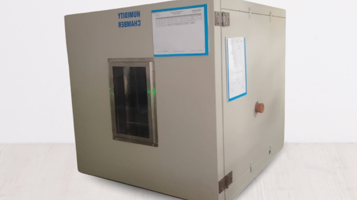
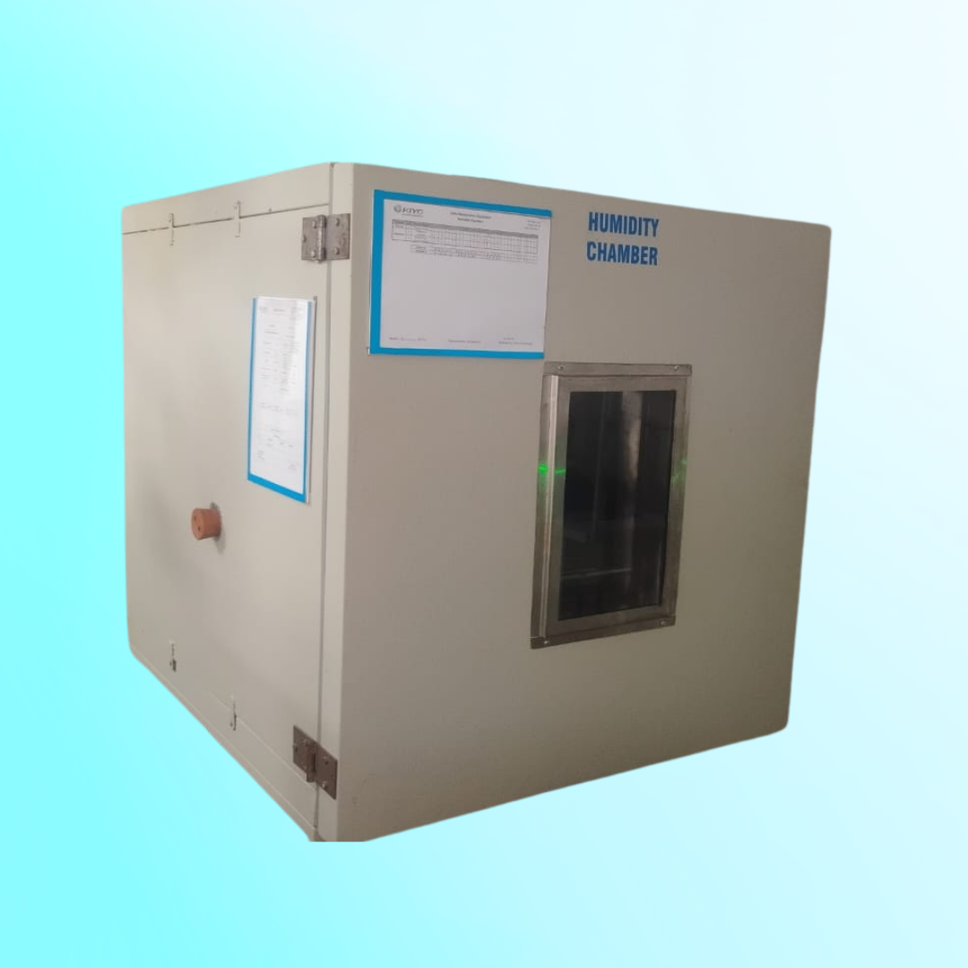
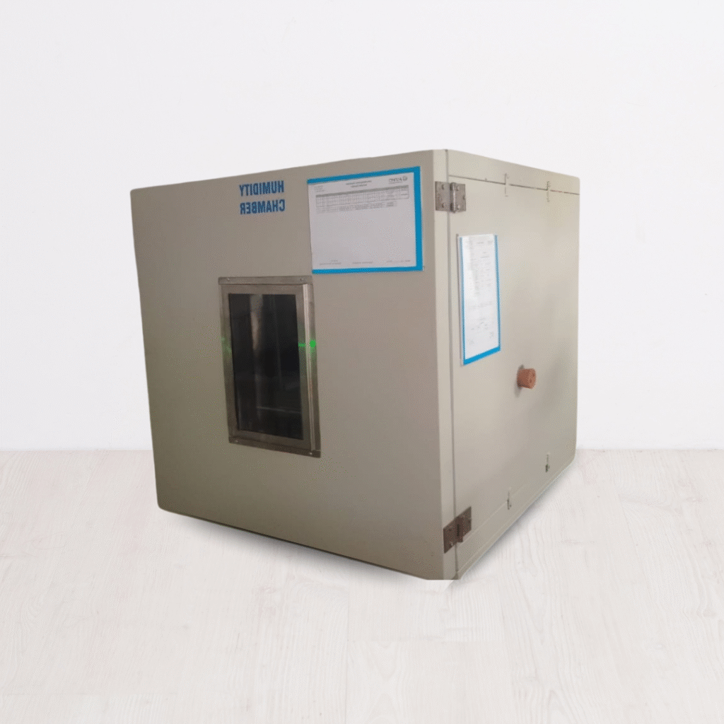
Alkali Resistance Testing in Chennai
A small river named Duden flows by their place and supplies it with the necessary regelialia. It is a paradise
Introduction
- Chennai, with its rapidly expanding construction, textile, and chemical manufacturing sectors, presents a unique set of environmental challenges for materials. One critical concern is resistance to alkali exposure—whether from cementitious environments, detergents, or industrial chemicals. Alkali resistance testing is a vital process used to evaluate how well materials such as coatings, textiles, plastics, and concrete additives can withstand prolonged exposure to high-pH (alkaline) conditions. This blog explores the relevance, standards, and testing procedures for alkali resistance, particularly in Chennai’s industrial landscape.

Significance of Alkali Resistance Testing
Alkali resistance is crucial in a variety of industries:
Construction Materials (e.g., paints, sealants, concrete additives): These materials come in contact with cement, which is highly alkaline.
Textiles & Geotextiles: Often used in chemically active or cleaning-intensive environments.
Plastic & Polymer Products: Used in industrial settings where chemical exposure is frequent.
Protective Coatings: Applied on structures exposed to harsh weather or marine environments.
In Chennai’s humid coastal climate and industrial zones, materials are often subjected to combined stress factors—humidity, heat, and chemical exposure—making alkali resistance a top priority for quality assurance.
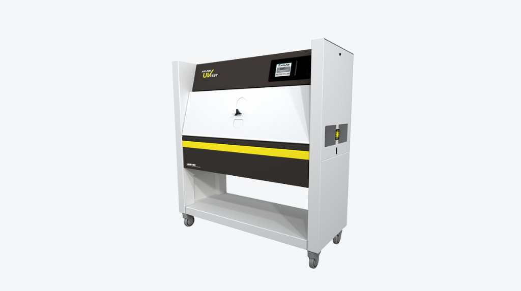
Standardized Testing Methods
Alkali resistance testing is conducted according to national and international standards. Some commonly referenced standards include:
ASTM D1308 – Standard Test Method for Effect of Household Chemicals on Clear and Pigmented Organic Finishes.
ISO 105-E04 – For textiles: Tests for color fastness to perspiration (alkaline solution).
IS 15477 (for Construction) – Guidelines for admix performance including resistance to alkali.
ASTM C267 – Chemical resistance of mortars and grouts (alkali exposure).
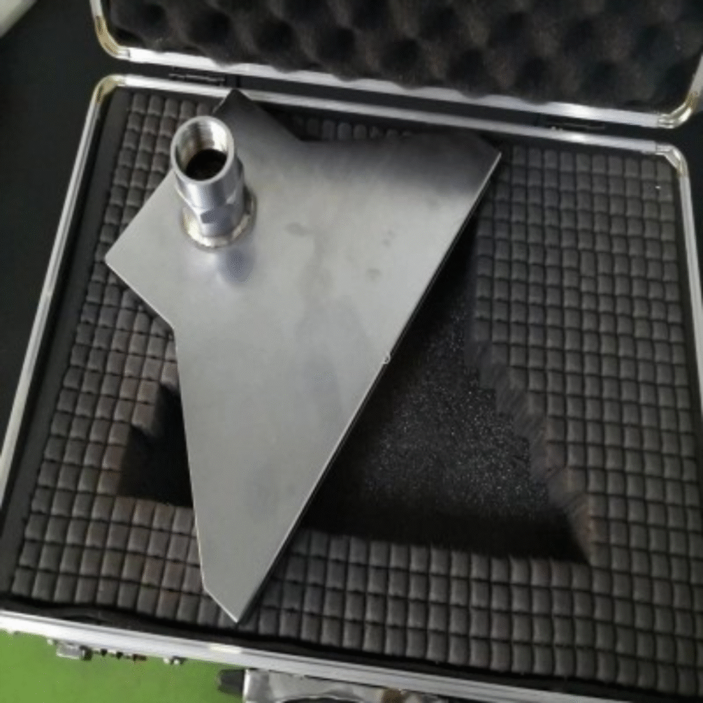
Specimen Preparation and Dimensions
Sample preparation depends on the material type:
Coatings and Paint Films: Typically applied on glass or metal panels, cured, and then immersed in an alkaline solution.
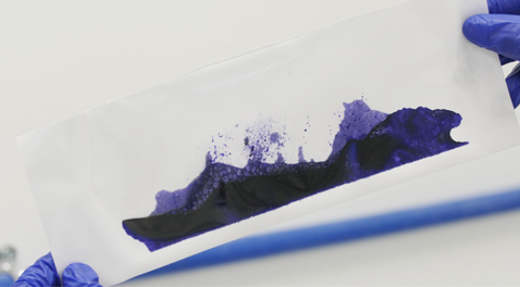
Textile Swatches: Cut into standard dimensions (e.g., 10×4 cm), subjected to alkaline solution, and assessed for fading, degradation, or color bleeding.
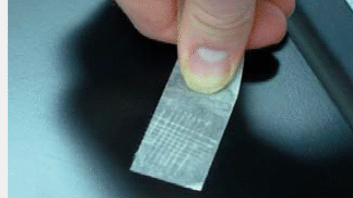
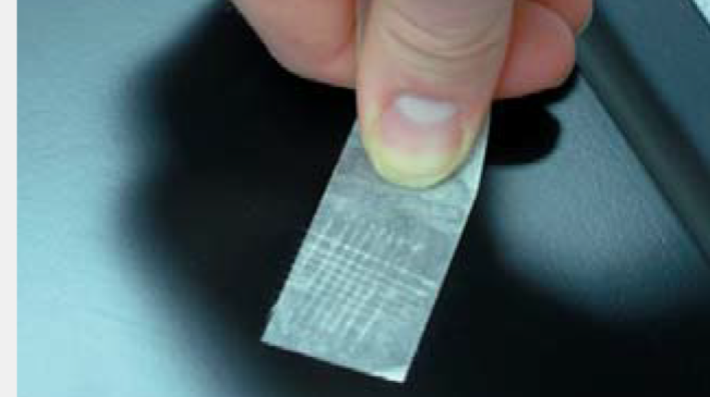
Polymer Sheets: Standard thickness and size depending on product category.
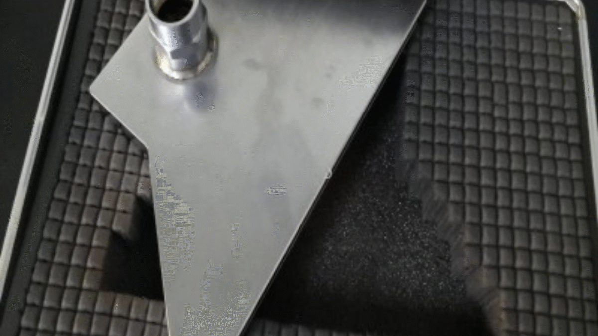
Mortar or Concrete Samples: Cubes or bars soaked in sodium hydroxide solution to evaluate mass loss or surface erosion.
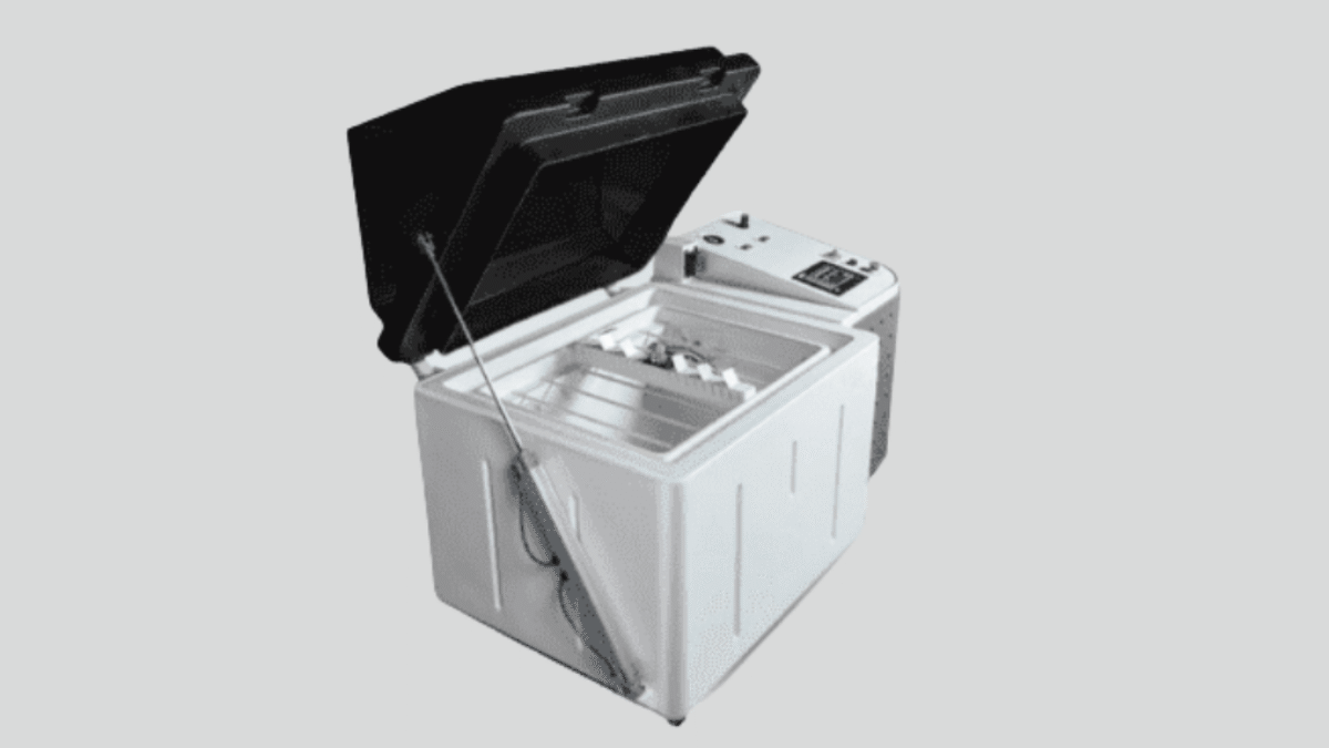
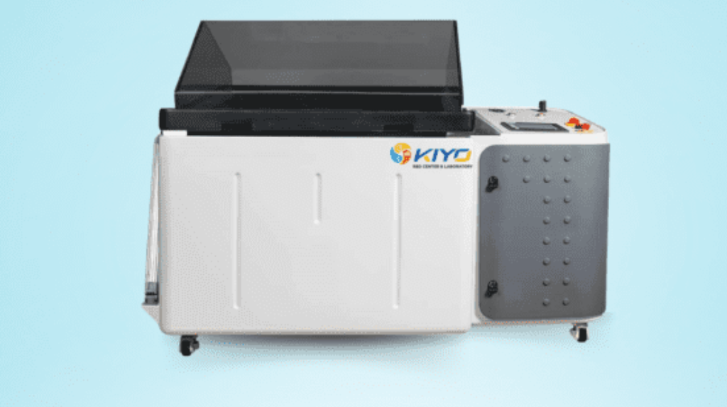
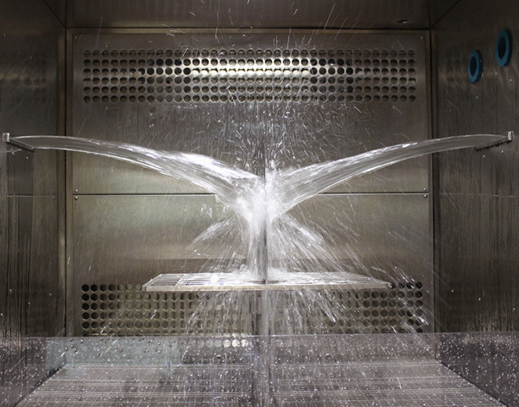
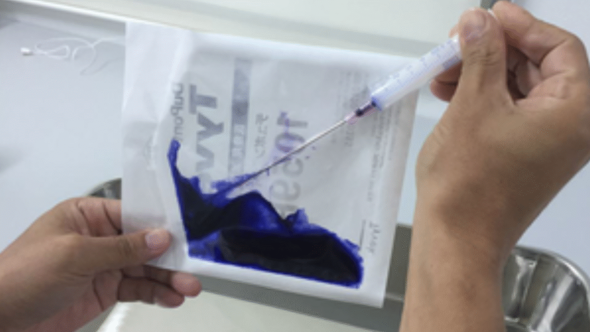
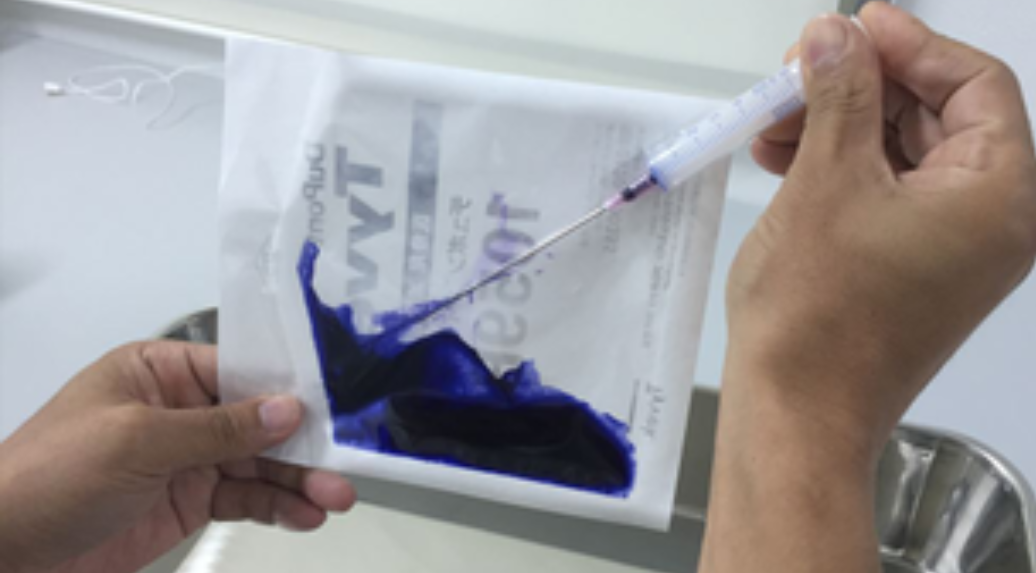
Test Procedure Overview
- Sample Immersion: Specimens are immersed in a standard alkaline solution (e.g., NaOH, Ca(OH)₂).
- Exposure Duration: Typically ranges from 24 hours to 7 days or longer.
- Observation and Evaluation:
Color change
Weight loss
Surface degradation
Structural integrity
- Documentation: Detailed visual observations, photographs, and weight measurements are recorded.
Components of a Typical Test Report
A comprehensive alkali resistance test report includes:
Test standard used (e.g., ASTM or ISO)
Material description and batch information
Alkaline solution concentration and pH
Immersion duration
Pre- and post-test weight
Visual inspection notes
Photographic evidence
Final evaluation and compliance statement
Implications of Alkali Resistance Data
Understanding alkali resistance helps in:
Product Development: Selecting the right formulation or raw materials.
Quality Control: Ensuring batch-to-batch consistency.
Compliance: Meeting industry and export standards.
Durability Forecasting: Estimating the service life of the product.
For Chennai-based manufacturers and developers, this data directly impacts project warranties, regulatory approvals, and brand reputation.
Other Considerations
Environmental Impact: Safe disposal of alkaline solutions is crucial.
Chennai-Specific Factors: High humidity and coastal proximity can accelerate chemical reactions.
Custom Testing Services: Labs in Chennai may offer tailored testing based on specific industrial use cases—like textile dye performance or waterproofing membranes.

Conclusion
- Alkali resistance testing is not just a compliance necessity—it’s a proactive step toward improving product performance and safety, especially in industrial hubs like Chennai. Whether you're a manufacturer, developer, or quality assurance manager, understanding how your materials respond to alkaline environments is essential for long-term success.